

PCB assembly affects LED downlight performance long before a fixture reaches a ceiling. A downlight can look bright during a brief inspection yet develop instability, uneven output, or early failures when assembly consistency is weak. I focus on how soldering, component placement, electrical connections, and heat transfer should be evaluated across every production batch.
PCB assembly influences LED downlight performance by creating the electrical and thermal connections that support the LEDs, driver interface, and heat sink.1 Consistent solder joints, controlled reflow processes, accurate component placement, and a well-executed thermal path help reduce avoidable instability. However, PCB assembly is only one part of overall downlight reliability; LED quality, driver design, optics, housing design, and installation conditions also matter.
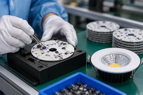
When I speak with importers, contractors, and product managers, I often hear one question first: “What PCB material or thickness do you use?” That is a reasonable starting point. Still, I believe buyers get a more useful answer when they also ask how reliably the PCB is assembled, connected, inspected, and tested in each production batch.
Why Does PCB Assembly Matter More Than Board Material Alone?
A buyer may see an acceptable PCB specification and assume the downlight will perform consistently. That assumption can create problems later. I have learned from production work that a suitable board material cannot compensate for weak solder joints, inaccurate placement, or poor heat transfer between the LED board and the fixture body.2
PCB assembly matters because the board must work as part of a complete electrical and thermal system, not as an isolated component. Board material and thickness can influence heat handling, but assembly quality determines whether LEDs and electronic parts are connected securely, positioned correctly, and thermally coupled to the heat sink across the production batch.
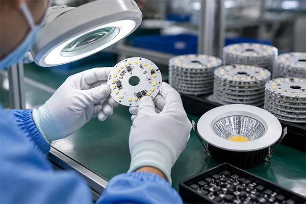
A PCB Is Part of a Larger Downlight System
I encourage procurement teams to evaluate an LED downlight as a system with several connected parts:
- LED light source: Produces light and heat during operation.
- PCB or MCPCB: Supports LED mounting and can help conduct heat away from the LEDs.
- Solder joints: Create electrical and mechanical connections.
- Thermal interface materials: Help transfer heat from the PCB to the heat sink.
- Heat sink or aluminum housing: Dissipates heat into the surrounding environment.
- LED driver: Regulates electrical power supplied to the LEDs.
- Optical components: Shape the beam and influence visual appearance.
- Assembly process: Determines whether these components work together consistently.
A thicker board or a particular board material may be appropriate for a certain design, but I would not treat either point as a complete quality verdict. For example, a correctly specified metal-core PCB can still underperform if the LED soldering process creates inconsistent joints or if the board does not make reliable contact with the heat sink.
In my experience, buyers should shift from a single-specification question to a process-focused question:
“How does the supplier control PCB assembly and thermal connection across every production batch?”
That question leads to more meaningful supplier discussions. It also helps technical teams compare quotations that may look similar on paper but differ in process control.
What Buyers Can Request During Evaluation
I recommend asking suppliers for practical evidence rather than relying only on general statements about “good PCB quality.”
| Evaluation Area | Useful Buyer Question | Why It Matters |
|---|---|---|
| PCB specification | What board type, thickness, and thermal design are used? | Establishes the intended design basis. |
| LED placement | How is component placement controlled? | Misalignment can affect soldering, optics, and thermal contact.3 |
| Reflow soldering | How is the soldering profile managed and checked? | Poor reflow conditions can create incomplete or stressed solder joints. |
| Thermal connection | How is the PCB coupled to the heat sink? | Poor contact can limit heat transfer. |
| Batch control | Are process settings consistent between production batches? | Helps reduce variation in large or repeat orders. |
| Inspection | What visual, electrical, and aging checks are performed? | Shows how the supplier screens for visible defects and early issues. |
At Upward Lighting, I view these checkpoints as part of manufacturing discipline. They do not make a fixture immune to every field condition, but they help us identify assembly issues before shipment and maintain a more consistent production flow.
How Can PCB Assembly Create Electrical Instability in LED Downlights?
Electrical issues can be difficult for buyers to detect during a short product review. A downlight may turn on normally at first, while an imperfect connection remains hidden until vibration, repeated switching, or heat cycling places stress on the assembly. This is why I consider soldering control a core procurement concern.
PCB assembly can create electrical instability when solder joints are incomplete, uneven, stressed, or poorly connected. Inconsistent reflow soldering and component placement may contribute to intermittent electrical contact, flickering, unstable output, or early failure.4 The PCB is not always the root cause, because drivers and other fixture components can also create similar symptoms.
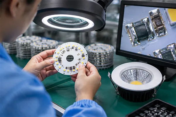
Solder Joints Are Functional Connections
A solder joint does more than hold a component in place. It creates an electrical path between the LED, PCB circuit, wiring points, and related components. If that path is not formed consistently, the downlight may have an intermittent connection.
Some assembly conditions that deserve attention include:
-
Insufficient solder paste
Too little solder can reduce joint strength or create incomplete electrical contact. -
Excess solder paste
Too much solder can contribute to bridging between contacts or inconsistent joint geometry. -
Uncontrolled reflow temperature profiles
Reflow soldering needs appropriate heating and cooling conditions for the specific components and materials. A poorly controlled profile may affect solder formation or introduce thermal stress. -
Component placement variation
If LEDs or electronic components are not positioned accurately, the soldering result and thermal contact may become less consistent. -
Contamination on surfaces
Dust, oxidation, moisture, or handling contamination can interfere with solderability and connection quality.5 -
Mechanical stress after soldering
Subsequent assembly steps, wire routing, fastening, or handling can place strain on connections if the fixture design or process is not controlled.
I do not suggest that every flicker complaint is caused by a solder joint. In LED downlights, flicker can also relate to driver compatibility, dimming systems, input power conditions, wiring, or installation practices. Still, PCB assembly should be part of the investigation because it directly affects electrical continuity.
Why First Power-On Is Not Enough
A fixture that turns on during initial inspection has passed only a limited check.6 It confirms that electricity can flow at that moment, but it does not fully demonstrate how every connection will behave under repeated operating conditions.
During production, I see value in combining several checks:
- Visual inspection for obvious soldering or placement issues
- Electrical functional checks
- Assembly verification before final closure
- Aging or burn-in screening
- Packaging checks that reduce avoidable transport damage
These controls are especially relevant for wholesalers, distributors, and local lighting brands that need stable repeat orders. One inconsistent batch can create after-sales exposure, replacement costs, and reputational damage that are much larger than a small unit-price difference.
Questions I Would Ask a Downlight Supplier
For purchasing managers and technical leads, I suggest practical questions such as:
- Is PCB assembly completed in-house, outsourced, or managed through both methods?
- How are soldering parameters controlled for each model?
- How are component-placement errors detected?
- What checks occur before the PCB is installed into the downlight housing?
- How are production changes documented between repeat orders?
- Can the supplier explain how it handles nonconforming units found during inspection?
Clear answers do not replace an application-specific technical review. However, they help buyers distinguish between a supplier that only lists components and a supplier that understands process consistency.
How Does PCB Assembly Affect Heat Management and Lumen Maintenance?
Heat is one of the most important practical considerations in an LED downlight. Buyers may focus on initial brightness, but I believe long-term output stability deserves equal attention. If heat does not move efficiently away from the LEDs, the fixture may face more stress during operation, even when the light appears satisfactory at first.
PCB assembly affects heat management by influencing the thermal path from the LED package through the PCB and into the heat sink. Poor contact, uneven mounting, incorrect thermal interface application, or inconsistent fastening can restrict heat transfer. Restricted heat transfer may contribute to faster lumen depreciation, color shift, or reliability concerns over repeated heat cycles.7
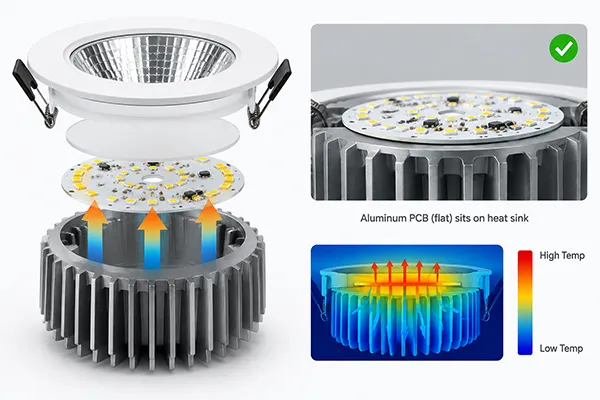
The Thermal Path Needs Continuous Contact
An LED downlight produces both useful light and heat. The fixture must move that heat away from the LED junction through a designed thermal path. While exact thermal performance depends on the complete design, I generally assess the path in this order:
- LED package
- Solder connection
- PCB or metal-core PCB
- Thermal interface material, if used
- Heat sink or aluminum fixture body
- Ambient air around the installed downlight
A weakness at any stage can affect the whole path. For example, a good heat sink design may not perform as intended if the PCB is not mounted flat against it. Similarly, thermal paste or another interface material must be applied in a consistent and suitable manner. Too little material can leave gaps. Too much material can also be problematic if it prevents close mechanical contact.8
Heat Management Is Not Only About PCB Thickness
I caution buyers against using PCB thickness as a shortcut for downlight quality. A thicker board may be used in some designs, but it does not independently confirm that heat is being managed well. The complete thermal result depends on several connected variables.
| Thermal Factor | Procurement Relevance |
|---|---|
| PCB construction | Indicates the intended heat-conduction design, but requires context. |
| LED mounting quality | Influences both electrical connection and heat transfer. |
| PCB flatness and fit | Helps determine contact with the heat sink. |
| Thermal interface application | Can reduce air gaps when correctly selected and applied. |
| Fastening method | Affects pressure and consistency of PCB-to-housing contact. |
| Heat sink geometry | Determines how effectively the housing can release heat. |
| Installation environment | Ceiling space, insulation, airflow, and ambient temperature can change operating conditions. |
I once reviewed a production sample where the visible parts looked nearly identical to another sample, yet the assembly sequence needed closer attention because the board-to-housing contact was not as consistent as expected. That kind of observation is why I prefer to inspect how parts are assembled rather than evaluate a downlight from a component list alone.
Heat Cycling Can Reveal Hidden Weaknesses
Repeated operation creates repeated heating and cooling. Different materials can expand and contract differently, which can place stress on solder joints, interfaces, and mechanical fasteners over time.9 I do not present aging tests as a laboratory lifetime prediction. Still, I consider thermal cycling behavior an important reason to maintain disciplined assembly controls.
For project contractors, this matters because installed downlights are expensive to access and replace. For importers and distributors, it matters because a batch that performs inconsistently can increase returns and service costs. A supplier should therefore be able to discuss both the downlight’s thermal design and the practical process used to assemble the PCB into the fixture.
Can 100% Aging Tests Replace PCB Assembly Process Control?
Many buyers value 100% aging tests, and I understand why. Aging can help screen for some early defects before products are packed and shipped. However, I do not believe buyers should confuse screening with prevention. A test at the end of production cannot fully replace controlled soldering, thermal assembly, and batch management earlier in the process.
A 100% aging test can help identify some early LED downlight defects10, such as immediate functional instability or assembly-related problems that appear during operation. However, aging tests do not prove full service-life reliability11 and cannot replace disciplined PCB assembly control, thermal design verification, component selection, and consistent manufacturing processes.
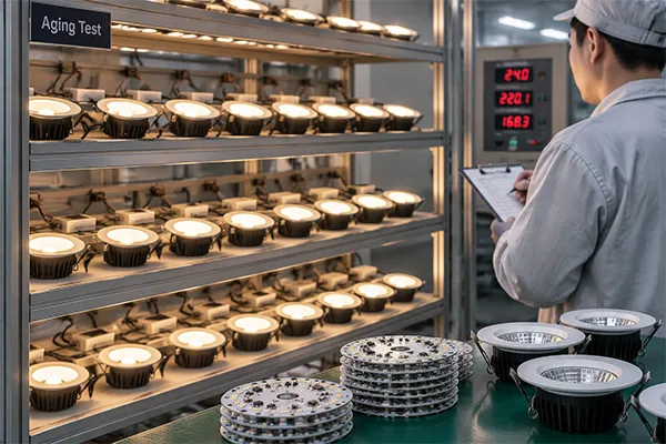
What Our Aging Test Screens For
At Upward Lighting, we conduct a 100% aging test lasting approximately 4 to 8 hours before shipment. I see this process as a practical quality-control checkpoint. It gives us an opportunity to observe products under operating conditions and identify some defects that may not be visible during a quick initial power-on inspection.
Depending on the model and production process, an aging stage may help reveal issues such as:
- Units that do not illuminate correctly
- Obvious unstable operation
- Certain early electrical connection problems
- Driver or LED failures that occur shortly after operation begins
- Visible output inconsistency that requires further inspection
When a unit shows an issue, our team can isolate it for inspection rather than allowing it to move directly into final packing. This supports shipment quality, particularly when customers need repeatable product performance across larger orders.
What Aging Tests Cannot Prove
I also believe transparency is important. A 4-to-8-hour aging test is not proof that a downlight will operate without issue for its full claimed or expected service life. It does not reproduce every installation environment, switching pattern, ceiling condition, voltage condition, dimming setup, or long-term heat cycle.
Aging tests also do not replace:
- Proper PCB layout and material selection
- Controlled solder-paste application
- Appropriate reflow soldering parameters
- Accurate LED and component placement
- Consistent PCB mounting to the heat sink
- Driver compatibility evaluation
- Incoming component inspection
- Batch-level process documentation
This distinction is useful for responsible supplier selection. I recommend that buyers ask suppliers not only whether they perform aging tests, but also how they control the production stages before the product reaches aging.
A Practical Supplier Evaluation Framework
For OEM and ODM downlight procurement, I suggest using a balanced evaluation framework.
| Area | What to Review | Why It Supports Better Decisions |
|---|---|---|
| Product specification | Wattage, CCT, beam angle, CRI, IP rating, dimensions | Confirms the fixture suits the project brief. |
| PCB assembly | Soldering, placement, inspection, mounting method | Addresses electrical and thermal consistency. |
| Thermal design | PCB-to-heat-sink path and housing structure | Helps evaluate heat-management intent. |
| Driver | Input range, dimming compatibility, protection features | Recognizes that the driver affects performance too. |
| Quality control | Incoming checks, in-process inspection, aging test | Shows how the supplier screens and manages defects. |
| Documentation | CE, RoHS, test reports, specifications | Helps buyers verify applicable market-entry requirements. |
| Supplier responsiveness | Quotation speed, sample support, change management | Supports smoother repeat-order management. |
Certifications such as CE and RoHS should be treated as documents that buyers verify for the relevant product model and destination market.12 I recommend qualified technical and regulatory review when a project has specific compliance, installation, or performance requirements.
Frequently Asked Questions
Does a thicker PCB make an LED downlight better?
A thicker PCB does not automatically make an LED downlight better. Board thickness is only one design factor. Buyers should also assess PCB construction, LED soldering quality, thermal contact with the heat sink, driver performance, housing design, and consistency across production batches.
Can poor PCB assembly cause LED downlight flickering?
Poor PCB assembly can contribute to flickering if solder joints or electrical connections are intermittent. However, flickering can also come from the LED driver, dimmer compatibility, input power conditions, wiring, or installation issues. A qualified evaluation should consider the whole fixture system.
What should I ask a supplier about PCB assembly?
I recommend asking how the supplier controls solder paste, reflow soldering, component placement, visual inspection, electrical testing, PCB-to-heat-sink mounting, and batch consistency. You can also ask how nonconforming products are isolated and corrected before shipment.
Does a 100% aging test guarantee LED downlight lifetime?
No. A 100% aging test can help identify some early defects during production, but it does not guarantee full service-life reliability. Long-term performance also depends on design, materials, assembly control, operating temperature, driver quality, installation conditions, and maintenance practices.
Why does thermal contact matter in LED downlights?
Thermal contact matters because LEDs generate heat during operation. The fixture needs an effective path from the LED and PCB to the heat sink and surrounding air. Poor contact can restrict heat transfer and may increase the risk of lumen depreciation, color change, or reliability concerns over time.
Conclusion
PCB assembly affects LED downlight performance because it connects the electrical path and supports the thermal path that LEDs need during operation. I recommend looking beyond PCB material or thickness alone. Buyers should assess solder-joint integrity, reflow control, component placement, PCB-to-heat-sink contact, aging-test procedures, and batch consistency. At Upward Lighting, we support OEM and ODM downlight sourcing with customized specifications, in-process quality control, and 100% aging tests before shipment. Contact us to discuss your downlight requirements and supplier-evaluation needs.
"[PDF] Advanced Materials for LED Lighting", https://www.energy.gov/sites/prod/files/2015/02/f19/haugaard_led-materials_sanfrancisco2015.pdf. LED luminaire guidance describes electrical interconnections and thermal pathways from the LED package to surrounding heat-dissipation structures as material elements of system performance. Evidence role: mechanism; source type: government. Supports: LED luminaires require electrical interconnections and a thermal path that transfers heat away from the LED package to maintain operating performance.. ↩
"[PDF] Accelerated Thermal Cycling and Failure Mechanisms For BGA and ...", https://ntrs.nasa.gov/api/citations/20000060832/downloads/20000060832.pdf. Electronics-reliability literature identifies solder-joint integrity and thermal-interface quality as independent contributors to assembly performance, so substrate selection alone does not establish reliability. Evidence role: general_support; source type: research. Supports: Assembly-related defects, including poor solder-joint formation and inadequate thermal interfaces, can affect electronics reliability independently of substrate selection.. Scope note: The source should support the general engineering principle; the relative importance of each factor depends on the specific downlight design and use conditions. ↩
"Thermal Induced Interface Mechanical Response Analysis of ...", https://pmc.ncbi.nlm.nih.gov/articles/PMC9228286/. Studies of surface-mount assembly show that placement error can alter solder-joint geometry and may compromise intended mechanical or optical alignment in assemblies designed with tight positional tolerances. Evidence role: mechanism; source type: paper. Supports: Placement accuracy affects solder-joint formation and, where component position is part of the optical or mechanical design, alignment performance.. Scope note: The optical and thermal consequences vary with package geometry, optical design, mounting method, and tolerance limits. ↩
"[PDF] EEE Parts Bulletin: Inspection of Area Array Package Interconnections", https://nepp.nasa.gov/files/18263/10_JPL%20EEE%20Parts%20Bulletin%20Special%20Edition%20Jan-2010.pdf. Reliability research on soldered electronic assemblies reports that defective or thermomechanically stressed solder joints can produce intermittent electrical continuity and eventual failure. Evidence role: mechanism; source type: paper. Supports: Defective solder joints and assembly variation can produce intermittent electrical behavior and reduce electronic-assembly reliability.. Scope note: Such evidence supports solder-joint failure mechanisms generally and does not establish that every instance of downlight flicker originates in PCB assembly. ↩
"[PDF] Printed Circuit Board Inspection and Quality Control – PCB Failure ...", https://ntrs.nasa.gov/api/citations/20180005658/downloads/20180005658.pdf. Electronics-assembly research recognizes surface oxidation and contamination as factors that can impair solder wetting and reduce the quality of soldered interconnections. Evidence role: mechanism; source type: research. Supports: Oxides, residues, moisture, and other contaminants can interfere with wetting and solder-joint formation.. ↩
"[PDF] organic & printed electronics", https://tsapps.nist.gov/publication/get_pdf.cfm?pub_id=854054. Reliability-testing guidance distinguishes a functional test, which confirms operation at the time of inspection, from reliability evaluation under specified environmental and operational stresses. Evidence role: definition; source type: institution. Supports: Functional testing and reliability qualification have different purposes: the former confirms operation at the time of test, while the latter evaluates performance over defined stresses and durations.. Scope note: The extent of assurance provided by any initial inspection depends on the test coverage, load conditions, and acceptance criteria. ↩
"[PDF] LED Luminaire Reliability: Impact of Color Shift - Department of Energy", https://www.energy.gov/sites/prod/files/2017/04/f34/lsrc_colorshift_apr2017.pdf. LED performance guidance reports that elevated operating or junction temperature can accelerate light-output depreciation, affect chromaticity, and increase reliability stress. Evidence role: mechanism; source type: government. Supports: Elevated LED junction temperature is associated with reduced light output maintenance, changes in chromaticity, and reliability risk.. Scope note: Actual degradation rates depend on the LED package, drive current, optical materials, thermal design, and operating environment. ↩
"[PDF] Thermal Interface Materials Selection and Application Guidelines", https://ntrs.nasa.gov/api/citations/20160001771/downloads/20160001771.pdf. Thermal-management research shows that interfacial air gaps and unnecessarily thick thermal-interface layers can increase contact thermal resistance between mating surfaces. Evidence role: mechanism; source type: education. Supports: Air gaps and excessive thermal-interface bond-line thickness can increase contact thermal resistance, while suitable application improves heat transfer across an interface.. Scope note: Optimal material amount and mounting pressure depend on the interface material, surface flatness, hardware, and mechanical design. ↩
"Thermal Fatigue Failure of Micro-Solder Joints in ... - PMC - NIH", https://pmc.ncbi.nlm.nih.gov/articles/PMC11123225/. Electronic-packaging studies identify differential thermal expansion during temperature cycling as a source of cyclic strain and fatigue in soldered interconnections. Evidence role: mechanism; source type: paper. Supports: Thermal-expansion mismatch between materials in electronic assemblies creates cyclic strain that can contribute to solder-joint fatigue.. Scope note: Failure susceptibility depends on temperature range, dwell time, joint geometry, material properties, and the number of cycles. ↩
"Electrical, Electronic, and Electromechnical (EEE) Parts Screening", https://llis.nasa.gov/lesson/814. Reliability-screening guidance describes burn-in as a process that can expose some early-life defects or weak units before products enter service. Evidence role: general_support; source type: government. Supports: Burn-in and related screening procedures are used to detect certain early-life defects or weak units before deployment.. Scope note: The defects detected depend on test duration, electrical load, temperature, sample handling, and the applicable failure mechanisms. ↩
"[PDF] Reliability technology for cardiac pacemakers III: a workshop report", http://nvlpubs.nist.gov/nistpubs/Legacy/SP/nbsspecialpublication400-50.pdf. Reliability-engineering literature treats burn-in as a screening method rather than proof of full service life, which requires defined life-test methods and operating assumptions. Evidence role: expert_consensus; source type: research. Supports: Burn-in screening is not equivalent to a service-life test or a complete reliability demonstration.. Scope note: A properly designed accelerated-life program can provide reliability estimates, but those estimates remain conditional on the tested stresses and statistical model. ↩
"EU - EU Legislation and CE Marking", https://www.trade.gov/country-commercial-guides/eu-eu-legislation-and-ce-marking. European Commission guidance states that CE marking and RoHS compliance depend on the applicable legislation, product category, conformity procedures, and supporting technical documentation. Evidence role: definition; source type: government. Supports: CE marking and RoHS obligations are tied to applicable EU legislation, product categories, conformity assessment, and technical documentation.. Scope note: Requirements can differ by product configuration, intended market, and applicable legislation; regulatory advice may be needed for a specific transaction. ↩